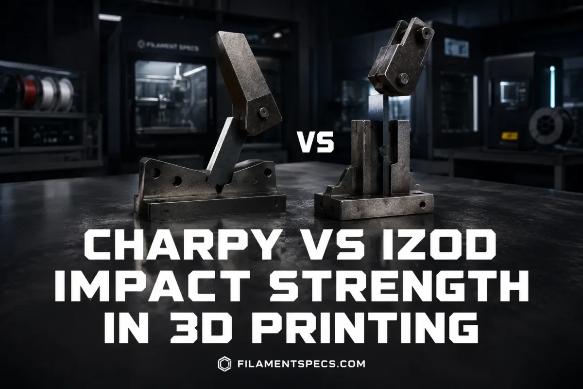
Charpy and Izod impact strength cannot be compared as if they were the same property. Both use a swinging pendulum to break a specimen, but Charpy supports the bar horizontally at two points while Izod clamps it vertically as a cantilever. The notch position, loading geometry, specimen dimensions, test standard, and reporting unit also differ. For 3D-printed parts, build orientation, raster direction, infill, layer bonding, and notch preparation add further variables. A higher value indicates greater absorbed impact energy only when the results were obtained under the same documented test conditions.
| Test Detail | Charpy | Izod | 3D Printing Implication |
|---|---|---|---|
| Specimen mounting | Horizontal bar resting on two supports | Vertical bar clamped at one end | The different constraint changes bending, crack initiation, and energy absorption. |
| Loading arrangement | Three-point bending | Cantilever bending | Layer interfaces may be loaded differently even when the same filament is tested. |
| Notch relative to impact | Notch normally faces away from the striker | Notch is normally on the impact side for the standard notched configuration | The crack approaches printed roads and layer boundaries from a different direction. |
| Common plastics standards | ISO 179-1 or ASTM D6110 | ISO 180 or ASTM D256 | The test name alone is insufficient; the complete standard designation is needed. |
| Common result format | Often area-normalized in ISO testing, such as kJ/m² | ASTM D256 commonly reports J/m; ISO 180 commonly reports kJ/m² | Numerical conversion does not make results equivalent because the fixtures and calculations differ. |
| Sensitivity to build orientation | High | High | Flat, on-edge, and upright specimens can produce different fracture paths. |
| Typical purpose | Material comparison, quality control, temperature studies, and printed-part research | Material comparison, resin quality control, and notch-sensitivity testing | The selected method should remain unchanged throughout a comparison. |
| Direct interchangeability | No | Compare only results produced with matching standards, units, specimen conditions, and print settings. | |
“Charpy” or “Izod” without the applicable ASTM or ISO standard does not fully describe an impact result.
What Pendulum Impact Strength Measures
A pendulum impact test records how much of the pendulum’s available energy is absorbed while a standardized specimen fractures. The machine releases a pendulum from a defined height. After striking the specimen, the pendulum rises to a lower height because part of its kinetic energy was consumed by deformation, crack initiation, crack growth, friction, and movement of the broken specimen.
ASTM D256 describes Izod pendulum testing as a measure of the energy required to break specimens with specified mounting, notching, and impact conditions. The standard also warns that specimens showing different failure types should not automatically be compared as though they produced equivalent results.[a] ASTM D6110 applies a related pendulum principle to notched Charpy specimens and uses a milled notch to create a controlled stress concentration.[b]
Impact strength is not the same as tensile strength. Tensile testing applies a slower, controlled pull. Pendulum testing applies rapid bending and fracture loading. A filament can have high tensile strength yet remain sensitive to a sharp notch or sudden impact.
How Charpy Loads the Specimen
In a Charpy test, the specimen lies horizontally across two supports. The pendulum strikes the middle of the bar, producing a three-point bending load. For the usual notched arrangement, the notch faces away from the pendulum so that the notch root is placed in the tensile side of the bent specimen.[i]
ISO 179-1 defines multiple specimen and notch configurations rather than one universal Charpy setup. The current non-instrumented plastics standard is ISO 179-1:2026.[c] ASTM D6110 is another Charpy method for notched plastic specimens, but an ASTM D6110 result should not be presented as equivalent to an ISO 179 result. Differences in specimen geometry, notch requirements, striker configuration, calculation, and reporting rules remain relevant even though both tests use the Charpy name.
For a printed bar, Charpy loading may drive the crack across continuous extrusion roads, through infill, along perimeter-to-infill boundaries, or between layers. Which path dominates depends on how the specimen was placed on the build plate and where the notch sits relative to the layer planes.
How Izod Loads the Specimen
In an Izod test, the specimen is held vertically and clamped near the notch. The free section extends above the clamp and is broken by the pendulum as a cantilever. In the standard notched arrangement, the notch is placed on the impact side so that its root enters the tensile zone created by bending.[i]
ASTM D256 is widely used for notched Izod testing of plastics and includes several procedures for different material behavior and notch-sensitivity questions.[a] ISO 180:2023 also covers Izod impact strength, but its test configurations and area-based reporting cannot be treated as ASTM D256 data merely because both use a vertically clamped specimen.[d]
The clamp introduces a local boundary condition that is absent from the Charpy setup. Small differences in clamping position, specimen thickness, surface condition, or notch placement can change the effective free length and fracture response. Layered specimens may also delaminate near the clamp or notch instead of forming the same crack path seen in a horizontally supported Charpy bar.
Why the Units Do Not Make the Tests Equivalent
Impact energy itself is measured in joules, but published impact strength is normally divided by a specimen dimension or remaining cross-sectional area. The calculation depends on the selected standard.
- ASTM D256 Izod: commonly reports absorbed energy per unit specimen thickness at the notch, usually in J/m or ft·lbf/in.
- ISO 180 Izod: normally reports energy divided by the remaining cross-sectional area, commonly in kJ/m².
- ISO 179 Charpy: uses an area-related impact-strength value, commonly reported in kJ/m².
- ASTM D6110 Charpy: follows its own specimen, correction, calculation, and reporting requirements and should retain its ASTM designation.
Converting J/m to kJ/m² requires a dimensional assumption, usually involving the specimen width remaining below the notch. Even when enough dimensional information is available for a mathematical conversion, the converted value is still an ASTM Izod result. It does not become an ISO Izod or Charpy result.
Do not rank two filaments by number alone when one TDS lists 120 J/m ASTM D256 and another lists 12 kJ/m² ISO 179. The apparent numerical difference combines dissimilar fixtures, normalization methods, specimen geometries, and possibly molded and printed samples.
Build Orientation Can Change the Fracture Path
Material-extrusion printing creates a directional structure rather than a uniform solid. Each deposited road has its own polymer orientation and thermal history. Adjacent roads contain interfaces, while successive layers depend on reheating and molecular diffusion for bonding. Voids, incomplete fusion, perimeter transitions, and seam locations can become preferred crack paths.
NIST’s review of polymer additive-manufacturing test methods describes how bead geometry, polymer orientation, diffusion, defects, and build construction can contribute to interlaminar failure.[e] Impact data therefore describes a material-process-orientation combination, not only the chemical name printed on the spool.
Flat Specimens
A flat specimen is normally printed with its broad face parallel to the build plate. Layers run through the specimen thickness, while perimeters and infill occupy the plane of the bar. Depending on raster angle and notch direction, the crack may need to cut across many deposited roads or may follow boundaries between adjacent roads.
On-Edge Specimens
An on-edge specimen places its narrow side on the build plate. This arrangement changes the relationship between the notch, perimeters, raster pattern, and layer planes. It can also produce a different number of layers through the width below the notch. On-edge results may exceed flat results in one material and fall below them in another because print settings and fracture direction interact.
Upright Specimens
Upright specimens place much of the impact-induced tensile stress across layer interfaces. Fracture may then proceed by interlayer separation rather than by tearing through continuous extrusion roads. Upright printing can also alter cooling history, specimen stability, surface texture, and notch accuracy.
A published PLA investigation using both ASTM D256 and ASTM D6110 found that impact results changed with infill configuration and density.[h] Its reported Charpy and Izod numbers should not be compared directly with one another, but the study demonstrates why slicer settings must accompany any impact-strength claim for printed specimens.
Raster, Walls, and Infill Affect What the Pendulum Breaks
Two specimens printed from the same spool can contain different load paths even when their external dimensions match. The following print variables can alter an impact result:
- Raster angle: determines whether the crack crosses deposited roads, follows them, or moves along road-to-road interfaces.
- Wall count: changes the amount of continuous perimeter material around the specimen and notch.
- Infill density: changes the amount of material available to deform and absorb energy.
- Infill pattern: changes local support, void shape, and crack direction.
- Layer height and extrusion width: alter road geometry, interface count, and local void structure.
- Nozzle temperature: influences flow and bonding between adjacent roads and layers.
- Cooling: affects crystallization, residual stress, bonding, and deformation behavior.
- Print speed: changes deposition time, thermal history, and fusion conditions.
- Seam placement: may introduce a local discontinuity near the highest-stress region.
Testing at nominally “100% infill” does not remove every variable. Slicer overlap, extrusion calibration, perimeter arrangement, internal gaps, and filament moisture can still change the actual structure. The specimen should be weighed or its apparent density recorded when the purpose is controlled material comparison.
The Notch May Control More Than the Filament
The notch creates a repeatable stress concentration so the fracture starts in a controlled region. Its angle, depth, root radius, surface finish, and position affect how easily a crack begins. A slightly sharper notch can reduce the measured energy even when the bulk material is unchanged.
ASTM D6110 requires a milled notch for its standardized notched Charpy method.[b] ASTM D256 also defines controlled notch geometry for its normal notched Izod procedures.[a] Printing the notch directly into the specimen can produce stair-stepped surfaces, rounded corners, seam defects, and orientation-dependent radii that differ from a machined notch.
A manufacturer may still use a printed notch as part of a documented internal or product-specific method. UltiMaker’s CPE technical data sheet, for example, identifies a printed Type 1eB notch, lists the Charpy configuration, and supplies the associated printer, layer height, infill, conditioning time, and orientation details.[f] That transparency makes the result useful within its stated context, but it should not be silently combined with values obtained from milled notches.
A useful data sheet states whether the notch was printed, molded, or machined. When notch preparation is absent, the impact value carries more uncertainty for printed-part comparison.
Printed Specimen Data vs Molded Resin Data
Some filament technical data sheets report tests performed on FFF specimens. Others report injection-molded bars made from the resin used to manufacture the filament. These datasets answer different questions.
| Specimen Source | What the Result Mainly Describes | Main Limitation for Filament Selection |
|---|---|---|
| Injection-molded resin specimen | The formulated polymer under the stated molding and conditioning process | Does not include FFF layer interfaces, raster paths, seams, or printing defects |
| 3D-printed standardized specimen | The filament combined with a stated printer, slicer profile, orientation, and test method | May not represent a different printer, orientation, wall count, or thermal history |
| Specimen cut from a printed component | The local structure of a particular printed part or production process | Geometry, extraction location, and surface preparation may limit comparison with standard bars |
| Finished component impact test | The behavior of the actual design under a defined loading event | Usually cannot be reduced to a universal filament impact-strength value |
UltiMaker’s CPE sheet explicitly states that its mechanical specimens were 3D printed and provides separate orientation information.[f] By contrast, the MakerBot Tough Filament technical sheet states that its ASTM D256 Izod figures were produced from injection-molded specimens made from the same resin used for the filament.[g] Both values may be valid within their declared methods, but they do not describe equivalent specimen structures.
Molded-resin impact strength is useful for understanding the potential of the formulation. Printed-specimen impact strength is more representative of a particular additive-manufacturing process. Neither alone guarantees how a finished part will survive drops, repeated strikes, vibration, or service loads.
How to Compare Impact Values on Filament Data Sheets
Before using an impact figure to choose between filaments, verify the following information:
- Test type: Charpy or Izod.
- Complete standard: ASTM D256, ASTM D6110, ISO 179-1, ISO 180, or another named method.
- Notch condition: notched or unnotched, including notch type and preparation method.
- Reporting unit: J, J/m, ft·lbf/in, kJ/m², or another stated unit.
- Specimen production: printed, injection molded, machined from sheet, or removed from a component.
- Print orientation: flat, on-edge, upright, XY, YZ, Z, or another defined coordinate system.
- Slicer conditions: layer height, raster, walls, infill, speed, temperatures, and cooling.
- Conditioning: test temperature, humidity exposure, drying, annealing, and time between printing and testing.
- Failure classification: complete break, partial break, hinge break, or non-break.
- Statistical reporting: number of specimens, mean, scatter, and any discarded results.
If one or more of these details are missing, the figure may still support internal product description, but its value for cross-brand ranking is limited. The safest comparison uses products tested by the same laboratory with the same specimen file, printer settings, orientation, conditioning, notch method, pendulum configuration, and calculation.
Selecting Charpy or Izod for a Printing Study
Neither method is universally better for 3D printing. The appropriate choice depends on the purpose of the test and the reference data that must be matched.
Use Charpy When
- Existing filament data is reported under ISO 179 or ASTM D6110.
- A three-point bending arrangement better matches the laboratory’s established polymer procedure.
- Multiple build orientations will be studied with controlled support conditions.
- Temperature-conditioned impact testing is part of the test program.
- The laboratory can machine and verify consistent notches when the selected standard requires them.
Use Izod When
- Existing resin or filament data is reported under ASTM D256 or ISO 180.
- The laboratory already uses a validated cantilever fixture and suitable pendulum.
- Notch sensitivity is the intended comparison.
- Quality-control limits were developed with the same Izod procedure.
- The vertical clamping arrangement is required by the applicable material specification.
Once a method has been chosen, changing from Charpy to Izod midway through a material-ranking program breaks the comparison chain. The same applies to switching from ASTM to ISO, from notched to unnotched bars, or from milled to printed notches.
What Impact Strength Does Not Predict
A pendulum result is a controlled specimen property, not a complete durability rating. It does not directly predict:
- Whether a finished enclosure will survive a drop onto concrete
- Resistance to repeated impact or fatigue
- Puncture resistance of a thin wall
- Performance around screw holes, inserts, clips, and sharp internal corners
- Behavior after UV exposure, water absorption, solvents, or thermal aging
- Impact response at temperatures not included in the test
- Damage caused by a differently shaped striker
- Energy absorption in flexible hinges or lattice structures
Component geometry can redistribute impact loads through ribs, curves, wall transitions, and local flexibility. For a functional printed part, standardized impact bars are best used to screen materials and process settings. A final design may still require a drop test, instrumented impact test, falling-weight test, or application-specific fixture.
Frequently Asked Questions
Is Charpy impact strength usually higher than Izod?
There is no fixed relationship. Charpy and Izod use different supports, notch positions, specimen dimensions, calculations, and sometimes different units. A higher Charpy number does not prove that the material performed better than it did in Izod testing.
Can an Izod value in J/m be converted to Charpy kJ/m²?
A dimensional conversion may be calculated when the required specimen measurements are known, but the result remains an Izod value from its original standard. Conversion cannot remove the effects of cantilever clamping, striker geometry, notch placement, or specimen configuration.
Should impact specimens be printed with 100% infill?
High infill is often used to reduce variation caused by sparse internal structures, but “100%” is not a complete test condition. Wall count, raster angle, extrusion width, overlap, flow calibration, and internal voids must also be controlled and reported.
Should the notch be printed or machined after printing?
Follow the selected standard. ASTM methods that require a milled notch should not be represented as standard-compliant when the notch was only printed. A printed notch may be used for a documented internal comparison, but its geometry and preparation method must be stated.
Why can upright specimens have lower impact strength?
Upright printing can place the impact-induced tensile load across layer interfaces. A crack may then separate layers with less energy than is required to tear through continuous extrusion roads. The outcome still depends on material, bonding conditions, notch direction, raster, and test geometry.
Can molded resin data be used for a printed part?
It can indicate how the underlying formulation behaves under the stated molding test, but it does not include FFF layer bonding, raster paths, seams, or voids. Printed-part design should use printed-specimen data produced under relevant settings whenever available.
Does a carbon-fiber filament always have better impact strength?
No. Short fibers can raise stiffness and alter crack paths, but they may also reduce elongation or make a formulation more notch-sensitive. The result depends on the polymer matrix, fiber content, fiber orientation, interlayer bonding, print direction, and test method.
Sources
- ASTM International — ASTM D256-26: Standard Test Methods for Determining the Izod Pendulum Impact Resistance of Plastics — Supports the Izod procedure, standardized specimen conditions, failure classifications, and J/m reporting context. (Official test standard.)
- ASTM International — ASTM D6110-18: Standard Test Method for Determining the Charpy Impact Resistance of Notched Specimens of Plastics — Supports the notched Charpy method and milled-notch requirement. (Official test standard.)
- International Organization for Standardization — ISO 179-1:2026, Plastics: Determination of Charpy Impact Properties, Part 1 — Supports the current non-instrumented ISO Charpy standard and its defined specimen configurations. (Official international standard.)
- International Organization for Standardization — ISO 180:2023, Plastics: Determination of Izod Impact Strength — Supports the current ISO Izod method and its defined test configurations. (Official international standard.)
- National Institute of Standards and Technology — Materials Testing Standards for Additive Manufacturing of Polymer Materials — Supports the discussion of polymer orientation, diffusion, defects, and interlaminar failure in printed materials. (Official government technical report.)
- UltiMaker — CPE Technical Data Sheet — Provides an example of Charpy data from printed specimens with stated orientation, conditioning, print settings, and printed-notch details. (Official manufacturer technical document.)
- MakerBot — Tough Filament Technical Specifications — Provides an example of ASTM D256 Izod data obtained from injection-molded specimens made from the filament resin. (Official manufacturer technical document.)
- Tanveer, Haleem and Suhaib — Effect of Variable Infill Density on Mechanical Behaviour of 3-D Printed PLA Specimen — Supports the influence of infill configuration on ASTM D256 and ASTM D6110 results for printed PLA specimens. (Peer-reviewed research article.)
- ZwickRoell — Charpy Impact Test — Supports the horizontal Charpy support arrangement, notch direction, three-point loading, and distinction from vertically clamped Izod testing. (Institutional materials-testing reference.)