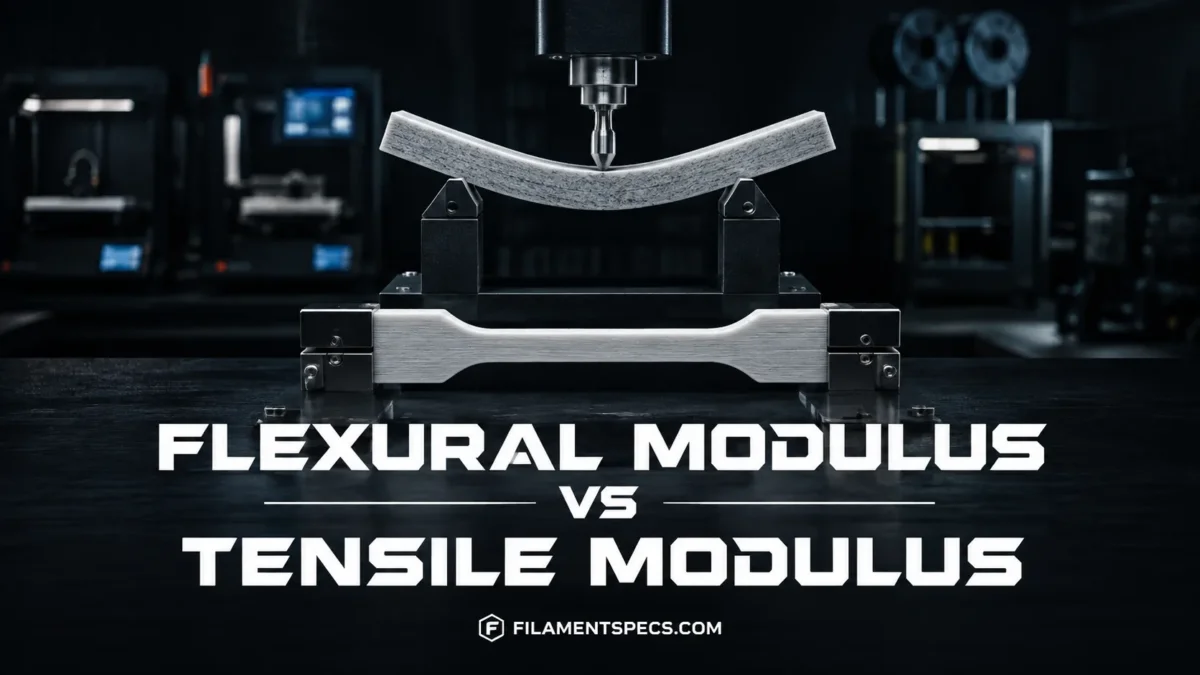
Flexural modulus and tensile modulus both describe stiffness, but they do not measure stiffness under the same loading condition. Tensile modulus describes resistance to elastic stretching during an axial pull, while flexural modulus describes resistance to elastic bending. For an ideal homogeneous, isotropic, linear-elastic material the two can be close, but plastics and especially FFF-printed parts can produce noticeably different values because bending, tension, compression, print orientation, specimen structure, and test procedure do not affect them in the same way.
| Property | Tensile Modulus | Flexural Modulus |
|---|---|---|
| Primary loading mode | Axial tension | Bending |
| What the specimen does | Stretches along its length | Deflects between supports |
| Stress state | Predominantly tensile through the gauge section | Tension on one side, compression on the other, with a neutral axis between them |
| Typical units | MPa or GPa | MPa or GPa |
| Common ASTM method | ASTM D638 | ASTM D790 |
| Common ISO method | ISO 527 | ISO 178 |
| A higher value indicates | Less elastic elongation under tensile stress | Less elastic bending under the specified flexural test |
| Especially useful for | Tension members, pull-loaded links, straps, tie points | Brackets, arms, beams, mounting plates, cantilevers |
| Directly interchangeable? | No. Similar units do not make the test results equivalent. | |
What Tensile Modulus Measures
A tensile test loads a specimen along its longitudinal axis. For plastics, ASTM D638 uses standard dumbbell-shaped specimens under defined conditions of pretreatment, temperature, humidity, and testing speed. ASTM also warns that tensile properties can change with specimen preparation, test speed, and environment.[a]
Tensile stress is force divided by the original cross-sectional area, while tensile strain describes the change in gauge length relative to the original gauge length. Within the relevant elastic region, tensile modulus represents the slope of the tensile stress-strain response:
Tensile modulus: Et = Δσ / Δε
The result is normally reported in megapascals (MPa) or gigapascals (GPa). A higher tensile modulus means that a specimen develops less elastic strain for a given tensile stress. It does not state how much stress the material can survive before yielding or breaking.
What Flexural Modulus Measures
Flexural modulus comes from a bending test rather than a direct pull. ASTM D790 covers flexural testing of unreinforced and reinforced plastics, while ISO 178 specifies flexural testing for rigid and semi-rigid plastics. The ISO method uses a freely supported beam loaded at midspan in a three-point bending arrangement.[b][d]
The stress distribution inside that specimen is fundamentally different from the stress state in a tensile coupon. In a simple bending condition, the material on one side of the beam is stretched while material on the opposite side is compressed. Between them is the neutral axis, where longitudinal bending stress passes through zero.
| Region of the Beam | Mechanical Condition |
|---|---|
| Outer surface on one side | Maximum longitudinal tensile stress |
| Neutral axis | Approximately zero longitudinal bending stress under simple beam assumptions |
| Opposite outer surface | Maximum longitudinal compressive stress |
Flexural modulus is calculated from the early flexural stress-strain response produced by this geometry. ISO 178 describes it as a modulus of elasticity in flexure and treats it as an approximation of Young’s modulus rather than as an automatically identical value.[d]
Same unit, different test: 3.0 GPa tensile modulus and 3.0 GPa flexural modulus may look interchangeable on a datasheet, but each number came from a different loading configuration and must be interpreted with its test method.
Why the Same Material Can Have Two Different Modulus Values
Classical beam theory starts from simplifying assumptions. For a homogeneous, isotropic material behaving linearly at small strain, the elastic modulus used for axial loading and bending can describe the same underlying elastic response. Real polymer measurements are less ideal.
Bending Combines Tension and Compression
A tensile modulus measurement mainly evaluates axial tensile behavior. A flexural specimen simultaneously places different regions of the material in tension and compression. If a polymer, composite, or printed structure responds differently to those loading modes, the modulus calculated from bending does not have to match the tensile value.
Stress Is Distributed Differently Through the Specimen
Nominal axial stress in the gauge region of a tensile specimen is intended to act across the section. Bending is different: longitudinal stress rises with distance from the neutral axis. The outer regions of a beam therefore carry much higher bending stress than material close to its center.
This distinction becomes especially relevant when a test specimen is not internally uniform. Voids, outer walls, fibre alignment, skin layers, infill, or different local bonding conditions can influence a flexural measurement differently from an axial tensile measurement.
Test Conditions Affect Plastics
ASTM D638 explicitly notes that measured tensile properties depend on specimen preparation, testing speed, temperature, and environment.[a] ISO 178 likewise states that specimens with different dimensions or preparation conditions may produce non-comparable flexural results and identifies test speed and conditioning as factors that can alter the measured behavior.[d]
That means a difference between two modulus numbers is not automatically evidence of an incorrect datasheet. The first check should be whether the values came from comparable specimen types and test conditions.
FFF Printing Adds Directional Stiffness
An injection-moulded test coupon and an FFF-printed coupon should not be treated as mechanically identical simply because both use the same polymer family. FFF creates roads, interfaces, pores, contour walls, and a build direction. NIST’s review of polymer additive-manufacturing test standards notes that established polymer test methods need careful application when they are used for additively manufactured materials.[f]
The printed part can therefore be anisotropic: its stiffness depends on the direction in which it is loaded. A load running along deposited roads can engage the extruded material differently from a load that must transfer across layer interfaces. Raster angle, build orientation, void distribution, and inter-road bonding can all change the measured response.
Flexural loading adds another layer to that problem. Because bending stress is highest near the outer surfaces, the structure located farthest from the neutral axis has more influence on bending response than material positioned close to the center. Depending on how the coupon is printed, perimeter layout and the orientation of deposited roads can therefore affect flexural stiffness differently from tensile stiffness.
Printed PLA and PLA-CF Show the Difference Directly
A peer-reviewed study by Reverte and colleagues tested FFF-printed PLA and short-carbon-fibre PLA in tensile and three-point bending configurations. The specimens followed ASTM D638 and D790 recommendations, used 100% infill, a 0.16 mm layer height, a 0.4 mm nozzle, 210 °C printing temperature, and a 2 mm/min mechanical-test loading rate. Three build orientations were evaluated.[g]
| Material | Build Orientation | Tensile Modulus (GPa) | Flexural Modulus (GPa) |
|---|---|---|---|
| PLA | Flat | 3.35 | 2.09 |
| PLA | On-edge | 3.29 | 1.71 |
| PLA | Upright | 3.05 | 1.91 |
| PLA-CF | Flat | 9.21 | 6.94 |
| PLA-CF | On-edge | 8.48 | 6.40 |
| PLA-CF | Upright | 3.35 | 2.34 |
These are results from one specific printing and testing setup, not universal PLA or PLA-CF properties. Different formulations, printers, orientations, and specimen conditions can produce different values.[g]
The table also shows why there is no dependable rule such as “flexural modulus equals tensile modulus multiplied by a fixed percentage.” Even with the material family held constant, the relationship changes with build orientation and reinforcement.
Carbon-Fibre-Filled Filaments Need Extra Care
Short-fibre-filled filaments can be much more direction-dependent than an unfilled polymer. Fibres tend to become oriented by melt flow and extrusion, so the printed road direction affects how effectively the reinforcement carries load. The PLA-CF study above illustrates this clearly: changing from flat to upright orientation reduced both tensile and flexural stiffness by large amounts, and the two modulus values did not move identically.[g]
A datasheet value for a carbon-fibre filament is therefore most useful when it states how the specimen was manufactured and oriented. A moulded composite value, an XY printed value, and a Z-oriented printed value can describe materially different load paths even if the product name is unchanged.
Material Modulus Is Not the Same as Part Bending Stiffness
A common design mistake is to search for a higher flexural modulus when the larger stiffness gain may be available through geometry. For a beam in the elastic range, bending stiffness is represented by the product:
Bending stiffness = E × I
E is the material modulus used in the beam model, while I is the second moment of area of the cross-section. MIT engineering beam-theory material gives the rectangular-section relation as:
I = bh3 / 12
where b is width and h is the section height in the bending direction.[h]
The cubic term matters. For an otherwise identical solid rectangular beam, doubling the section height makes I eight times larger. Under the same simplified elastic beam conditions, that can reduce bending deflection far more than a modest change from one filament modulus to another.
Design distinction: flexural modulus describes a material response measured in bending. The stiffness of an actual bracket or beam also depends on its length, cross-section, supports, wall structure, load location, and print orientation.
When Tensile Modulus Is the Better Number
Tensile modulus is the more direct stiffness metric when the important service load mainly pulls the part along its axis. Examples include a printed link in tension, a tie member, a hanging connector, or a component where axial elongation affects alignment.
If two candidate materials were tested under equivalent tensile conditions, the material with the higher tensile modulus should undergo less elastic axial strain at the same tensile stress. That comparison still says nothing by itself about fracture, impact tolerance, fatigue, or long-term creep.
When Flexural Modulus Is the Better Number
Flexural modulus becomes more informative when the printed component behaves primarily like a beam or plate. Cantilever brackets, sensor arms, mounting tabs, equipment supports, long holders, and flat panels often fail a functional requirement because they bend too much before material strength becomes the immediate limit.
For those parts, flexural modulus can give a more direct material-level indication of bending resistance. It still cannot predict the finished part on its own because the section geometry and FFF structure remain part of the stiffness calculation.
| Design Requirement | Property to Check First | Why |
|---|---|---|
| Limit axial stretching | Tensile modulus | Directly relates tensile stress to elastic tensile strain |
| Limit bending of a bracket or arm | Flexural modulus plus section geometry | Bending response depends on both material stiffness and beam geometry |
| Prevent failure under pulling load | Tensile strength | Modulus measures stiffness, not maximum tensile stress |
| Prevent failure under bending | Flexural strength | Flexural modulus does not state the bending failure limit |
| Carry a constant load for hours or months | Creep data | Short-duration modulus does not describe long-term deformation by itself |
| Remain stiff at elevated temperature | Temperature-dependent modulus and thermal data | Room-temperature modulus may not represent the service condition |
| Mixed tension, bending, and shear | Multiple mechanical properties | No single modulus represents a combined load case completely |
Flexural Modulus Is Not Flexural Strength
Modulus describes stiffness in the elastic or specified low-strain region. Strength describes a stress associated with yielding, maximum load, or failure according to the test definition. A material can therefore have a high flexural modulus and still reach its flexural strength limit earlier than a more compliant material.
The same separation applies in tension. A high tensile modulus means low elastic strain for a given tensile stress; it does not guarantee high tensile strength.
| Loading Mode | Stiffness Property | Strength Property |
|---|---|---|
| Tension | Tensile modulus | Tensile strength |
| Bending | Flexural modulus | Flexural strength |
Can Tensile Modulus Be Converted to Flexural Modulus?
There is no general conversion factor that reliably turns a tensile modulus into a flexural modulus for 3D printing filaments. A formula such as “tensile modulus × 1.2” has no universal basis.
The relationship may be close for some homogeneous materials tested in a small-strain elastic range, but polymer formulations, fibre reinforcement, anisotropy, test speed, conditioning, specimen dimensions, and FFF architecture can move the measurements apart. ISO 178 also treats the measured flexural modulus as an approximate Young’s modulus rather than declaring the values interchangeable.[d]
Avoid calculated substitutions in datasheets: if only tensile modulus is published, it can provide a broad indication of material stiffness, but it should not be relabelled as a measured flexural modulus.
How to Compare Datasheet Values Correctly
Two modulus numbers are most useful when the accompanying test conditions are comparable. ASTM D638 and D790 both define controlled test procedures, and ISO likewise warns that specimen and test conditions affect comparability.[a][d]
- Test method: confirm whether the value is tensile or flexural and identify the ASTM, ISO, or manufacturer method.
- Specimen origin: distinguish injection-moulded, machined, extruded, and 3D-printed coupons.
- Print orientation: check whether the test direction follows deposited roads or crosses layer interfaces.
- Internal structure: note infill density, raster arrangement, wall construction, and whether the specimen is effectively solid.
- Material formulation: PLA, PETG, PA, and other family names cover multiple blends and additive packages.
- Reinforcement: short carbon or glass fibres can introduce stronger direction dependence.
- Conditioning: moisture history and pre-test conditioning can change polymer response.
- Temperature: room-temperature stiffness should not automatically be applied to a warmer service environment.
- Test speed: polymer response can depend on loading rate.
- Reported status: distinguish a typical value from a guaranteed minimum or specification limit.
A value from a moulded resin datasheet can still be useful for understanding the base formulation, but it should not be presented as the measured modulus of a printed part. FFF introduces additional structure and orientation that the moulded specimen did not contain.[f]
ASTM D638 vs ASTM D790
ASTM D638-22 is the active ASTM method for tensile properties of plastics. It covers tensile testing of reinforced and unreinforced plastics using standard dumbbell-shaped specimens under controlled conditions.[a]
ASTM D790-25 is the active ASTM method for flexural properties of unreinforced and reinforced plastics and electrical insulating materials. Its flexural configuration evaluates a beam supported at two points and loaded in bending.[b]
ASTM notes that D638 and ISO 527 address the same general subject but differ in technical content; D790 and ISO 178 likewise address the same general flexural subject while differing technically.[a][b] Results reported under different standards should therefore retain their test labels rather than being merged as though the procedures were identical.
ISO 527 vs ISO 178
ISO 527-2:2025 specifies tensile test conditions for moulding and extrusion plastics and works with the general principles in the ISO 527 series. The 2025 edition includes updated specimen references aligned with ISO 20753.[c]
ISO 178:2019 remains the published ISO standard for determining flexural properties of rigid and semi-rigid plastics. ISO currently lists it as due for revision, while ISO/DIS 178 Edition 7 is under development.[d][e]
For a filament datasheet, the standard designation is therefore part of the measurement. Recording only “modulus: 3.5 GPa” removes information needed to determine whether the value represents tension, bending, a printed specimen, or another test condition.
Frequently Asked Questions
Is flexural modulus usually higher than tensile modulus?
No fixed ordering applies to all plastics or printed filaments. The two values may be close, flexural modulus may be higher, or tensile modulus may be higher. Material behavior, reinforcement, specimen geometry, orientation, conditioning, and the test procedure all affect the relationship.
Is flexural modulus the same as Young’s modulus?
Not exactly. Young’s modulus normally refers to elastic modulus obtained from uniaxial stress-strain behavior, while flexural modulus is obtained from bending. ISO 178 describes flexural modulus as an approximate value of Young’s modulus rather than an automatically identical measurement.[d]
Which modulus matters more for a 3D-printed bracket?
If the bracket mainly behaves as a cantilever or beam, flexural modulus is generally the more directly relevant material-level stiffness value. The finished bracket still depends heavily on section height, length, wall structure, load position, and print orientation.
Can tensile modulus be used if a manufacturer does not publish flexural modulus?
It can provide a general indication of how stiff the material is, particularly for material screening, but it should not be treated as a measured flexural modulus. For bending-sensitive design work, flexural test data from comparable printed specimens is preferable.
Does a higher flexural modulus mean a filament is stronger?
No. Higher flexural modulus means greater resistance to elastic bending under the specified test conditions. Flexural strength is a separate property describing the stress associated with the material’s flexural strength limit.
Why can two datasheets for the same filament type show very different modulus values?
The products may use different polymer grades, additives, fibre contents, moisture conditions, specimen preparation methods, print settings, orientations, or test standards. A material family name such as PLA or PA-CF does not define one universal mechanical property value.
Sources
- ASTM International — ASTM D638-22, Standard Test Method for Tensile Properties of Plastics — Supports the tensile test scope, current ASTM version, specimen conditions, and limits on direct comparison of tensile data. (Official standards organization.)
- ASTM International — ASTM D790-25, Standard Test Methods for Flexural Properties of Unreinforced and Reinforced Plastics and Electrical Insulating Materials — Supports the flexural test method, current ASTM version, and bending-test interpretation. (Official standards organization.)
- International Organization for Standardization — ISO 527-2:2025, Plastics — Determination of Tensile Properties — Part 2 — Supports the current ISO tensile test conditions for moulding and extrusion plastics. (Official international standards organization.)
- International Organization for Standardization — ISO 178:2019, Plastics — Determination of Flexural Properties — Supports three-point flexural testing, conditioning effects, flexural modulus interpretation, and the status of the published standard. (Official international standards organization.)
- International Organization for Standardization — ISO/DIS 178, Edition 7 — Supports the current development status of the next ISO 178 edition. (Official international standards organization.)
- National Institute of Standards and Technology — Materials Testing Standards for Additive Manufacturing of Polymer Materials: State of the Art and Standards Applicability — Supports caution when conventional polymer mechanical-test methods are applied to additively manufactured polymer parts. (U.S. national measurement institute.)
- Reverte et al. — Mechanical and Geometric Performance of PLA-Based Polymer Composites Processed by the Fused Filament Fabrication Additive Manufacturing Technique — Supports the printed PLA and PLA-CF tensile/flexural modulus data, specimen orientations, ASTM-based tests, and printing conditions. (Peer-reviewed Materials journal article.)
- MIT OpenCourseWare — Engineering Beam Theory — Supports the bending-stiffness relation EI, neutral-axis mechanics, and the rectangular-section relation I = bh³/12. (Massachusetts Institute of Technology engineering course material.)