
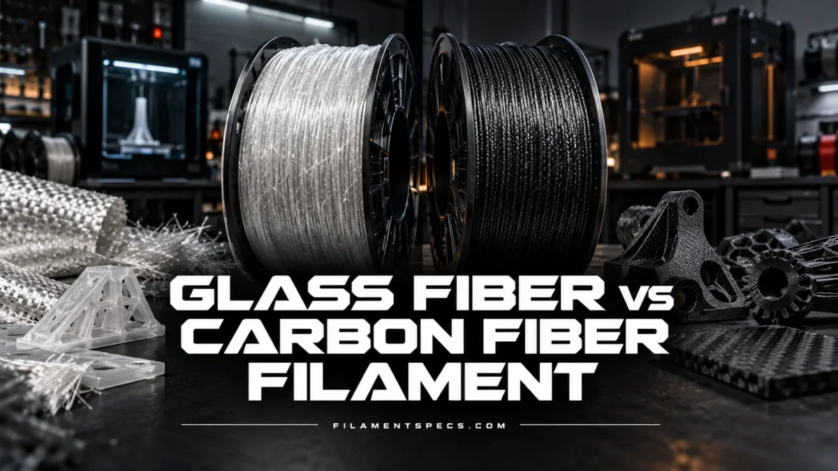
Carbon-fiber-filled filament is usually the better starting point when maximum stiffness and low deflection matter, while glass-fiber-filled filament can be a better fit when a different toughness balance, electrical insulation, lighter-colored formulations, or cost control matters. Neither reinforcement is automatically stronger in every direction. For a useful comparison, the polymer matrix, fiber loading, moisture condition, print orientation, and test method must be kept as similar as possible.
| Property or Requirement | Carbon-Fiber-Filled Filament | Glass-Fiber-Filled Filament |
|---|---|---|
| Stiffness | Usually the stronger advantage; suited to parts where deflection must be minimized | High relative to many unfilled polymers, but often below a comparable CF grade |
| Tensile strength | Can be higher in the print plane, but depends on matrix, loading, and orientation | Can approach or exceed CF in some directions or formulations |
| Z-direction performance | Fiber reinforcement does not remove dependence on interlayer bonding | Also controlled heavily by layer adhesion; some formulations can outperform a comparable CF grade |
| Impact behavior | High stiffness does not guarantee higher impact resistance | May provide a different toughness balance; test method and formulation matter |
| Part density | Can be lower for an otherwise comparable formulation | Can be somewhat higher because glass reinforcement is denser |
| Heat performance | May improve HDT within a given polymer family | Can also provide high HDT; the base polymer still defines the temperature class |
| Electrical behavior | Do not assume conductivity from the CF label alone | Generally selected more naturally where electrical insulation is desired, subject to product data |
| Nozzle wear | Abrasive; wear-resistant nozzle recommended | Abrasive; wear-resistant nozzle recommended |
| Moisture sensitivity | Primarily controlled by the polymer matrix | Primarily controlled by the polymer matrix |
| Appearance | Usually dark, matte, and visibly carbon-filled | Can support lighter-colored formulations depending on the product |
These are material-selection tendencies, not guaranteed properties. A PA6-CF filament should be compared with a PA6-GF filament before drawing conclusions about the reinforcement itself.
The Polymer Matrix Comes Before the CF or GF Label
The letters CF and GF describe the reinforcement, not the entire filament. A commercial composite filament also contains a thermoplastic matrix such as PA6, PA12, PET, PETG, PP, PPA, or PPS, plus formulation-specific additives. That matrix controls much of the melting behavior, moisture response, chemical resistance, interlayer bonding, and usable temperature range.
Comparing PA6-CF with PET-GF and attributing every difference to carbon versus glass fiber would therefore be misleading. The PA6 and PET matrices already behave differently before either reinforcement is considered.
Fair comparison order: same polymer matrix → similar reinforcement content → same conditioning state → same print orientation → same test method. Only after those variables are controlled does the CF-versus-GF distinction become meaningful.
Fiber percentage also needs context. Polymaker identifies Fiberon PA6-CF20 as containing 20 wt% carbon fiber and PA6-GF25 as containing 25 wt% glass fiber.[c] [d] Even though the products share a PA6 matrix and closely matched test procedures, the reinforcement fractions are not identical. Their data provide a useful real-world comparison, but not a laboratory experiment in which fiber chemistry is the only variable.
A Same-Matrix Comparison: PA6-CF20 vs PA6-GF25
The dry mechanical data for these two PA6 composites show why a single statement such as “carbon fiber is stronger” is too broad. Both data sheets report printed specimens, use the same ISO test families for the properties compared below, and specify 100% infill for their mechanical specimens. The manufacturer also states that the specimens were annealed at 100°C for 16 hours before the reported dry-property testing.[a]
| Property | PA6-CF20 | PA6-GF25 |
|---|---|---|
| Density at 23°C | 1.17 g/cm³ | 1.20 g/cm³ |
| XY Young’s modulus, ISO 527 | 8,636.5 MPa | 5,356.9 MPa |
| Z Young’s modulus, ISO 527 | 3,759.5 MPa | 3,375.9 MPa |
| XY tensile strength, ISO 527 | 109.3 MPa | 80.1 MPa |
| Z tensile strength, ISO 527 | 54.0 MPa | 60.7 MPa |
| XY bending modulus, ISO 178 | 7,037.6 MPa | 4,314.2 MPa |
| XY bending strength, ISO 178 | 161.0 MPa | 133.8 MPa |
| XY unnotched Charpy impact strength, ISO 179 | 24.0 kJ/m² | 27.4 kJ/m² |
| XY notched Charpy impact strength, ISO 179 | 11.0 kJ/m² | 10.0 kJ/m² |
PA6-CF20 values are reported in the manufacturer’s current technical data sheet.[a] PA6-GF25 values come from the corresponding PA6-GF25 technical data sheet.[b] The manufacturer describes these as typical values for comparison rather than guaranteed design limits.
The clearest CF advantage in this pair is stiffness. The dry XY Young’s modulus is about 8.64 GPa for PA6-CF20 versus 5.36 GPa for PA6-GF25. XY tensile strength follows the same direction, at 109.3 MPa versus 80.1 MPa.
The Z result is different. PA6-GF25 is reported at 60.7 MPa in Z tensile strength, while PA6-CF20 is 54.0 MPa. The material with the higher XY tensile strength is not automatically the material with the higher Z tensile strength.
Stiffness, Strength, and Toughness Give Different Answers
Stiffness describes resistance to elastic deformation. Young’s modulus and bending modulus are therefore important when a bracket, jig, fixture, optical mount, or machine component must remain dimensionally stable under load. This is where carbon-fiber-filled grades often show their clearest advantage.
Strength describes the stress a specimen can withstand before the relevant failure criterion is reached. It is not interchangeable with stiffness. A part can be very rigid yet still fail at a layer interface, stress concentration, thin section, or poorly oriented feature.
Toughness and impact resistance introduce another response. In the PA6 pair, the dry unnotched Charpy result is 27.4 kJ/m² for GF25 and 24.0 kJ/m² for CF20, while the notched values are much closer at 10.0 and 11.0 kJ/m² respectively.[a] That mixed result is more informative than declaring either reinforcement universally “tougher.” Geometry, notch sensitivity, orientation, moisture, and matrix behavior all change the failure mode.
For a low-deflection part, modulus may matter more than ultimate tensile strength. For a clip, latch, impact-loaded housing, or part that must tolerate strain, elongation and impact data can matter more than having the highest modulus.
XY and Z Loading Can Change Which Filament Looks Better
Short-fiber FFF composites are anisotropic: their mechanical response depends on direction. Research on short-carbon-fiber polyamide parts has shown that deposition direction and fiber alignment contribute directly to anisotropic tensile and fracture behavior.[e]
During extrusion, short fibers tend to develop orientation along the deposited road. A load applied within the printed plane can therefore benefit from the reinforced extrusion paths. A load applied through the Z axis must cross interfaces between deposited layers, so interlayer bonding remains a major part of the load path.
This is why a high XY modulus should not be treated as evidence of equally high through-thickness performance. In the PA6 example, CF20 has a large advantage in XY modulus and XY tensile strength, but GF25 records the higher dry Z tensile strength. Part orientation can therefore matter as much as the reinforcement choice for brackets, tabs, bosses, screw mounts, and other features loaded away from the print plane.
Heat Resistance Still Starts with the Base Polymer
Adding carbon or glass fiber can improve dimensional stability and heat-deflection behavior within a formulation, but it does not move every reinforced polymer into the same temperature class. A CF-filled PLA remains fundamentally different from a CF-filled PA, PPA, or PPS.
| ISO 75 Test Load | PA6-CF20 | PA6-GF25 |
|---|---|---|
| 1.8 MPa | 173°C | 157°C |
| 0.45 MPa | 215°C | 191°C |
Both technical data sheets state that the HDT specimens were annealed at 100°C for 16 hours.[a] [b]
The practical limitation is the conditioning state. An annealed HDT value should not automatically be assigned to an as-printed part. Crystallinity and dimensions can change during annealing, so an application that depends on heat resistance should use the exact product’s conditioning procedure and allow for dimensional verification after treatment.
Moisture Can Change the Comparison More Than the Fiber Type
This becomes especially important with nylon matrices. Carbon or glass reinforcement does not remove PA6’s moisture response. The PA6-CF20 and PA6-GF25 data sheets publish both dry and moisture-conditioned mechanical results, allowing the scale of the change to be seen directly.
| Property | CF20 Dry | CF20 Wet | GF25 Dry | GF25 Wet |
|---|---|---|---|---|
| XY Young’s modulus | 8,636.5 MPa | 2,508.1 MPa | 5,356.9 MPa | 1,793.6 MPa |
| XY tensile strength | 109.3 MPa | 54.7 MPa | 80.1 MPa | 40.2 MPa |
| Z tensile strength | 54.0 MPa | 25.5 MPa | 60.7 MPa | 26.3 MPa |
| XY elongation at break | 2.1% | 7.0% | 2.4% | 4.2% |
| XY notched Charpy impact | 11.0 kJ/m² | 35.6 kJ/m² | 10.0 kJ/m² | 28.0 kJ/m² |
For the wet-condition data, Polymaker states that specimens were annealed and then immersed in 60°C water for 48 hours. Average reported specimen moisture content was 5.30% for PA6-CF20 and 4.57% for PA6-GF25.[a] [b]
The change is not simply “worse when wet.” Stiffness and tensile strength fall sharply in both formulations, while elongation and Charpy impact values increase. Moisture plasticizes the nylon matrix, changing how the composite deforms and fails.
Dry filament and a dry finished part are different conditions. Drying before printing can improve extrusion quality, but a nylon part can later absorb moisture from its service environment. Mechanical data should therefore be matched to the condition in which the printed component will actually operate.
Printing Temperature and Hardware Are Mostly Product-Specific
There is no universal CF temperature and no universal GF temperature. A PLA-CF filament may run on hardware that cannot reach the processing temperature required by PA6-CF, while PPS-CF belongs to another temperature range entirely. The matrix and the manufacturer’s formulation set the printing window.
The two Fiberon PA6 products provide a useful controlled example because both specify a 280–300°C nozzle range, a 40–50°C build plate, cooling fan off, and room-temperature chamber conditions. Both also specify drying at 100°C for 10 hours in their technical data sheets.[a] [b] Those settings belong to these products and should not be transferred to unrelated CF- or GF-filled polymers.
Both Reinforcements Can Wear a Brass Nozzle
Carbon-fiber-filled and glass-fiber-filled filaments should both be treated as abrasive unless the product manufacturer states otherwise. The PA6-CF20 and PA6-GF25 data sheets each warn that brass-nozzle abrasion occurs frequently and recommend a wear-resistant nozzle such as hardened steel or ruby.[a] [b]
The manufacturer gives an approximate nine-hour brass-nozzle life for both of these particular products. That number should not be generalized to all reinforced filament because wear also depends on fiber content, formulation, nozzle material, extrusion rate, temperature, and total filament throughput.
Nozzle diameter is another product-level variable. A larger bore can be useful with some heavily filled materials, but the reinforcement label alone does not establish a minimum diameter. If a technical data sheet specifies a minimum nozzle size, that value should take precedence over a generic CF-versus-GF rule.
Part Weight: Carbon Fiber Does Not Make Every Print Dramatically Lighter
Carbon-fiber-filled grades can offer an attractive stiffness-to-weight balance, but the finished filament density depends on the polymer, reinforcement percentage, and other additives. The PA6 comparison is a useful scale check: CF20 is listed at 1.17 g/cm³ and GF25 at 1.20 g/cm³.[a] [b]
For two fully solid parts with the same 100 cm³ external material volume, those densities correspond to roughly 117 g and 120 g before considering printing voids or geometry changes. In this pair, the stiffness difference is much larger than the mass difference. Designers seeking a lightweight component should therefore compare stiffness per unit mass rather than assuming that a CF label guarantees a large weight reduction.
Carbon Fiber in the Name Does Not Guarantee Electrical Conductivity
Carbon fibers themselves can conduct electricity, but conductivity in a polymer composite depends on whether the conductive reinforcement forms a sufficiently connected network through the material. Fiber length, concentration, orientation, dispersion, and the insulating polymer between fibers all affect that network.
The PA6 example makes the limitation clear. Both PA6-CF20 and PA6-GF25 are reported with surface resistance above 1012 Ω under the manufacturer’s ANSI/ESD S11.11 measurement entry.[a] [b] The presence of 20 wt% carbon fiber in PA6-CF20 therefore should not be treated as proof that the printed material is electrically conductive or suitable for a specified ESD resistance range.
Do not select a CF-filled filament for an electrical requirement from the material name alone. Use the product’s measured surface or volume resistivity and the required electrical specification for the application.
Surface Finish and Color Can Affect the Practical Choice
Carbon reinforcement normally gives the filament a dark appearance and often produces the matte technical finish associated with CF-filled materials. That can make layer texture less visually prominent on some parts, but the result still depends on fiber loading, layer height, temperature, extrusion consistency, and the underlying polymer.
Glass reinforcement does not impose the same black carbon color, so GF-filled formulations can be available in lighter shades. Neither reinforcement is intended for optical transparency once enough short fiber is present to create an engineering composite.
For dimensional fixtures and machine components, appearance usually ranks below stiffness, temperature capability, moisture condition, and load direction. For housings or visible functional parts, color availability may become a legitimate selection constraint.
Choosing Between GF and CF for the Actual Load Case
| Application Requirement | Better Starting Point | Reason | Main Check Before Printing |
|---|---|---|---|
| Low-deflection machine bracket | CF | Higher stiffness is often the main benefit | Load orientation and Z strength |
| Precision jig or fixture | CF or GF | Both can provide reinforced dimensional behavior | Required rigidity, temperature, and matrix |
| Lightweight rigid component | CF | Often offers the stronger stiffness-to-weight case | Actual filament density and impact requirement |
| Impact-loaded component | Formulation dependent | Stiffness alone does not predict impact failure | Notched and unnotched impact data |
| Part loaded strongly through Z | Formulation dependent | Interlayer bonding can dominate the result | Z tensile data and print orientation |
| Electrically insulating housing | GF is a natural candidate | Glass reinforcement avoids assuming a conductive carbon network | Measured electrical properties of the finished material |
| High-temperature fixture | CF or GF in an appropriate matrix | Matrix and conditioning determine the temperature class | HDT test load, annealing state, and service temperature |
| Colored functional part | GF often offers more flexibility | No black carbon reinforcement is required | Available formulation and pigment |
| Living hinge or highly flexible clip | Often neither | Short-fiber reinforcement generally prioritizes rigidity over repeated flexing | Elongation, fatigue, and unfilled alternatives |
The most reliable selection sequence is to choose the polymer family for service temperature, moisture, chemicals, and environmental exposure first. Then determine whether low deflection, tensile strength, impact tolerance, electrical behavior, or mass has priority. Only after those requirements are clear should CF versus GF become the deciding variable.
For rigidity-driven parts, CF is usually the stronger starting point. For applications where a different toughness balance, electrical insulation, appearance, or product cost matters more than maximum stiffness, GF deserves a direct comparison rather than being treated as a lower-grade substitute.
FAQ
Is carbon fiber filament always stronger than glass fiber filament?
No. Carbon-fiber-filled filament can deliver higher stiffness and higher tensile strength in some directions, but the result depends on the polymer, reinforcement percentage, fiber orientation, conditioning, and test method. In the PA6 example used here, CF20 has higher dry XY tensile strength, while GF25 has higher dry Z tensile strength.
Which is stiffer, glass fiber or carbon fiber filament?
Carbon-fiber-filled grades commonly have the advantage when stiffness is the main requirement. The same-matrix PA6 example reports 8,636.5 MPa dry XY Young’s modulus for CF20 and 5,356.9 MPa for GF25.[a] Exact values should still be checked for the specific products being considered.
Does glass fiber filament resist impact better than carbon fiber filament?
Not universally. Impact behavior depends on the matrix, fiber loading, specimen orientation, notch condition, and moisture state. The dry PA6 data show GF25 slightly higher in unnotched Charpy impact strength, while the notched values are close and CF20 is slightly higher.[b]
Can carbon fiber filament be assumed to conduct electricity?
No. Conductive fibers do not guarantee a conductive printed composite. The reinforcement must form an appropriate conductive network through the polymer. Fiberon PA6-CF20, for example, is reported with surface resistance above 1012 Ω, so its CF label alone is not evidence of low electrical resistance.[a]
Do CF and GF filaments both require a hardened nozzle?
A wear-resistant nozzle is the safer baseline for short-fiber-filled materials. Both PA6-CF20 and PA6-GF25 technical data sheets warn about brass-nozzle abrasion and recommend hardened steel, ruby, or another wear-resistant nozzle.[a] Product-specific nozzle guidance should still be followed.
Which filament absorbs more moisture, CF or GF?
The polymer matrix usually matters more than the CF or GF label. A nylon-based CF filament and a nylon-based GF filament can both require aggressive drying and dry storage, while filled materials based on another polymer can behave differently. Reinforcement should not be treated as a substitute for the matrix’s moisture specification.
Sources
- Polymaker — Fiberon PA6-CF20 Technical Data Sheet V1.1 — Supports PA6-CF20 mechanical, thermal, electrical, moisture, density, drying, annealing, and nozzle-wear data. (Official manufacturer technical data sheet.)
- Polymaker — Fiberon PA6-GF25 Technical Data Sheet V1.0 — Supports PA6-GF25 mechanical, thermal, electrical, moisture, density, drying, annealing, and nozzle-wear data. (Official manufacturer technical data sheet.)
- Polymaker — Fiberon PA6-CF20 Product Information — Confirms the PA6 matrix and 20 wt% carbon-fiber content. (Official manufacturer product documentation.)
- Polymaker Wiki — Fiberon PA6-GF25 — Confirms the PA6 matrix and 25 wt% glass-fiber content. (Official manufacturer technical documentation.)
- Composite Structures — Anisotropy and Ageing Effect on the Mechanical Behaviour of 3D-Printed Short Carbon-Fibre Composite Parts — Supports the role of deposition direction, short-fiber alignment, and anisotropy in FDM polyamide composites. (Peer-reviewed research article.)